It should be no secret that pushrods transmit the reciprocating motion of the valve lifters to the rocker arms, but choosing the best pushrod for a high performance engine is anything but simple. When acted upon by an aggressive camshaft profile in an environment where high valve spring pressures are present, pushrods are exposed to extreme shocks, stress and harmonic vibrations as the valves are forced to open and slam shut. Pushrods are subjected not only to compressive forces but lateral, or side forces as well due to the angle of operation between lifter and rocker. Stiffness/ rigidity are obvious concerns. In this article we’ll try to address a variety of pushrod performance issues.
Check for runout
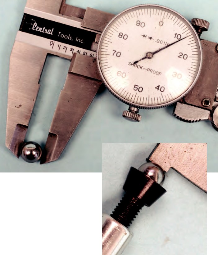
While this may seem obvious, before installing any pushrod (new or used), check each for straightness. This can be done in several ways. You can roll the pushrod across a piece of flat glass. Roll the pushrod slowly and look for a gap between the pushrod and glass surface. If the pushrod doesn’t roll smoothly across the glass (wobbles or bumps), it’s bent and must be discarded. While you can carefully chuck the pushrod in a drill press or lathe to check for wobble, it’s far too easy to damage the pushrod surface, plus you face the variable of off-center mounting in the chuck. If the spindle or chuck has runout, or if the pushrod isn’t chucked squarely, it will appear to have runout. A safe method is to employ a pushrod checking stand. This is a bench-top stand that positions the pushrod horizontally. As you slowly rotate the pushrod, a dial indicator monitors runout at the pushrod’s center of length. Pushrods should have zero runout. If excess runout is found, it’s best to replace it, although the manufacturer may be able to straighten it. Again, this is basic info but an area that should not be ignored.
Pushrod length
Obviously, pushrod length is critical in obtaining optimum valvetrain geometry. One of the primary goals is to allow the rocker arm to contact the tip of the valve stem at the center of the valve stem tip during rocker arm operation, transferring kinetic energy from the cam and lifter to the rocker arm and valve, while minimizing deflection and harmonics. If the pushrod is too short, the rocker arm may concentrate its contact at the outboard area of the valve stem. If too long, contact may be concentrated too far inboard on the stem tip. Running the rocker-to-valve off-center can result in side-loading of the valve, inducing an off-center path of the valve stem within the guide. While this may not be critical in a low-rpm grocery-getter, this can eventually cause premature guide wear or other problems under high-load/high-rpm use.
Since we’re focusing on optimized high performance engines here, as opposed to by-the-numbers rebuilding of a stock low performance engine, we really need to be aware of the importance of optimizing valvetrain geometry. A number of engine modifications can alter this geometry, including running higher-lift camshafts (higher lift means a smaller base circle, which lengthens the distance from lifter to rocker, which relocates the rocker tip to valve contact path); milling the cylinder heads and/or block decks, which shortens the distance, requiring shorter pushrods; running longer valve stems, etc. A number of variables can throw the rocker arm contact path at the valve out of whack.
In order to measure and check for pushrod length, the camshaft and lifters must be installed in the block (solid lifters should be used for checking, even if you intend to run hydraulics). The head must be equipped with valves and springs. While you can check using your real-world springs, this job is much easier if you swap out with light checking springs. Checking springs are readily available from any cam/spring maker.
Once the head is loaded (valves and springs installed), install the cylinder head using the exact type and thickness of head gasket that you intend to use during final assembly. Tighten/torque the head to specification.
A length-adjustable checking pushrod is required. These are available in a variety of length ranges. Some feature a 2-piece construction and others feature 3-piece construction. Regardless, a checking pushrod features multi-piece design that features threaded adjustment. Some are laser-etched with reference marks (instructions may say that one full turn is equal to 0.050” in length) and the body is laser-etched with the minimum length. With the checking pushrod fully collapsed (threaded to its shortest length), you can determine final length by counting the number of revolutions as you adjust the pushrod (increasing length). If, for example, the short length is 7.000” and you rotated it 3 full turns to achieve proper length (and if one full turn equals 0.050”), add 0.150” to the starting length of 7.000”. This would indicate the need for a 7.150”-long pushrod.
Text and photos by Mike Mavrigian. AERA sponsored article. Read the full article here: